Joystick

A joystick is a gaming control device. The C64 is compatible with an old standard first used in the Atari 2600 gaming console; the same standard used on the VIC-20, the C128 and the Amigas.
Joysticks that are compatible with the 64 have a stick that the user may push in one of eight directions, and a "fire" button. The control stick is mechanically connected to four switches; "up", "down", "left", and "right". Pushing the stick in a direction in between two of these "cardinal directions" activates two of the four switches.
Some Commodore compatible joysticks may have more than one such fire button, but in those cases both buttons will "do" the same things in a game; the software has no way of determining which fire button is used. Together with the directional switches for the control stick, a standard joystick requires five connections and a common ground wire.
Autofire[edit | edit source]
Some joysticks have a feature known as "auto-fire", to help out in those games where the best strategy is to shoot, shoot, shoot all the time: An oscillator delivers fast repeating pulses to the line normally connected to the fire button(s). Some people have made hardware "add-ons" that adds auto-fire capability to any joystick.
Joysticks as seen from the C64[edit | edit source]
Joysticks connect to the two control ports at the rightmost end of the C64. Inside the machine, the five switch lines from the joysticks connect to ports A and B in CIA #1; in parallel with the keyboard matrix. This is the reason why a joystick, especially one connected to control port #1, causes the machine to "type" characters when the joystick is operated.
A joystick on port #1 is read through address 56321/$DC01, and one on control port #2 are read via address 56320/$DC00. In each byte,
- Bit 0 (weight 1) goes low if the "up" switch is activated,
- Bit 1 (weight 2) goes low if the "down" switch is activated,
- Bit 2 (weight 4) goes low if the "left" switch is activated,
- Bit 3 (weight 8) goes low if the "right" switch is activated,
- Bit 4 (weight 16) goes low if the fire button is pressed.
Analog lines in the control ports[edit | edit source]
Besides ground and five inputs for the switches and buttons, the control ports also provides +5V (the aforementioned auto-fire feature is "fed" from this supply line) and two analog inputs, designed as "ohmmeters": These analog lines are mostly used for paddles, but despite the possibility to use these lines for an analog joystick (which can sense much more subtle movements to the stick than the four directional switches), such joysticks have never seen much use on the 64.
Programming[edit | edit source]
Assembler[edit | edit source]
Programming joystick routines in Assembler:
- Method: Bit test
BASIC[edit | edit source]
The memory addresses 56321 (Control Port 1) and 56320 (Control Port 2) contain the exact position of the joystick. These positions can be read with the BASIC-Command PEEK.
10 PRINT PEEK(56320): GOTO 10
RUN
Break with RUN/STOP .
Some values generated by pressed keys from the keyboard and the output of the joystick match (e.g. pressing space in some programs can be substituted for pressing fire), so the keyboard must be deactivated while the addresses of the joysticks are read. That can be achieved with POKE 56322,224. With POKE 56322,255 or with the key-combination RUN/STOP +RESTORE can activate the keyboard again.
| Position | 56321 Port 1 | 56320 Port 2 | 56321 Port 1 Fire pushed |
56320 Port 2 Fire pushed |
|---|---|---|---|---|
| middle (no move) | 255 | 127 | 239 | 111 |
| up | 254 | 126 | 238 | 110 |
| down | 253 | 125 | 237 | 109 |
| left | 251 | 123 | 235 | 107 |
| right | 247 | 119 | 231 | 103 |
| up left | 250 | 122 | 234 | 106 |
| up right | 246 | 118 | 230 | 102 |
| down left | 249 | 121 | 233 | 105 |
| down right | 245 | 117 | 229 | 101 |
Which means that Joystick at Port 2 can be simulated by holding space and pressing:
M for Fire
F1/F2 for Up
Z for Down
C for Left
B for Right
Combination (eg. Up+Left+Fire) works fine, although it is rather bothersome to punch that in.
Tested on Commodore 128D original keyboard
Starting with the Commodore 128 (BASIC v7), the JOY command was introduced.
Example Listing[edit | edit source]
- Example 1
This BASIC-program uses the joystick (port 2) to move an arrow on the screen.
 10 S=2: X=150: Y=150: V=53248: GOTO 100
 15 J=PEEK(56320): IF J=127 THEN 15
 20 IF J=111 THEN POKE 56322,255:END
 25 IF J=123 THEN X=X-S
 30 IF J=119 THEN X=X+S
 35 IF J=125 THEN Y=Y+S
 40 IF J=126 THEN Y=Y-S
 45 IF J=122 THEN Y=Y-S: IF J=122 THEN X=X-S
 50 IF J=118 THEN Y=Y-S: IF J=118 THEN X=X+S
 55 IF J=117 THEN Y=Y+S: IF J=117 THEN X=X+S
 60 IF J=121 THEN Y=Y+S: IF J=121 THEN X=X-S
 65 IF X=>252 THEN X=10
 70 IF X=<10 THEN X=252
 75 IF Y>254 THEN Y=44
 80 IF Y<44 THEN Y=254
 85 PRINT CHR$(147);CHR$(158);CHR$(17);"X-POS:";X;" Y-POS";Y
 90 POKE V,X:POKE V+1,Y: GOTO 15
100 FOR Z=832 TO 853 : POKE Z,0: NEXT Z
105 FOR Z=832 TO 853 STEP 3: READ J: POKE Z,J: NEXT Z
110 POKE V+21,1: POKE  V+39,7: POKE V+33,0: POKE V+29,1
115 POKE 56322,224: POKE 2040,13: GOTO 85
120 DATA 240, 224, 224, 144, 8, 4, 2, 1
Hint: Replace the lines 51-58 with this code for bit wise joystick input handling.
51 IF (J AND 1)=0 THEN Y=Y-S
52 IF (J AND 2)=0 THEN Y=Y+S
53 IF (J AND 4)=0 THEN X=X-S
54 IF (J AND 8)=0 THEN X=X+S
- Example 2
This BASIC program reads out both joystick ports and shows the pushed joystick arm (method: bit test).
10 J=NOT PEEK(56321)
15 B=NOT PEEK(56320)
20 PRINT CHR$(147);"JOYSTICKTEST 2012"
30 IF (J AND1) THEN PRINT "1-V ";
35 IF (B AND1) THEN PRINT "2-V ";
40 IF (J AND2) THEN PRINT "1-Z ";
45 IF (B AND2) THEN PRINT "2-Z ";
50 IF (J AND4) THEN PRINT "1-L ";
55 IF (B AND4) THEN PRINT "2-L ";
60 IF (J AND8) THEN PRINT "1-R ";
65 IF (B AND8) THEN PRINT "2-R ";
70 IF (J AND16)THEN PRINT "1-F ";
75 IF (B AND16)THEN PRINT "2-F ";
80 GOTO 10
Pictures[edit | edit source]

-
 Competition Pro 5000
 -
 Competition Pro 5000 Star
 -
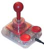 Competition Pro 5000 Extra
 -
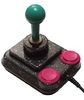 Competition Pro 5000 Spezial
 -
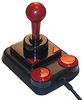 USB / Retro


-

-
 Quickshot II
 -
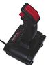 Quickshot II plus
 -
 Quickshot II Turbo
 -
 Quickshot VII


Links[edit | edit source]
| Wikipedia: Joystick |